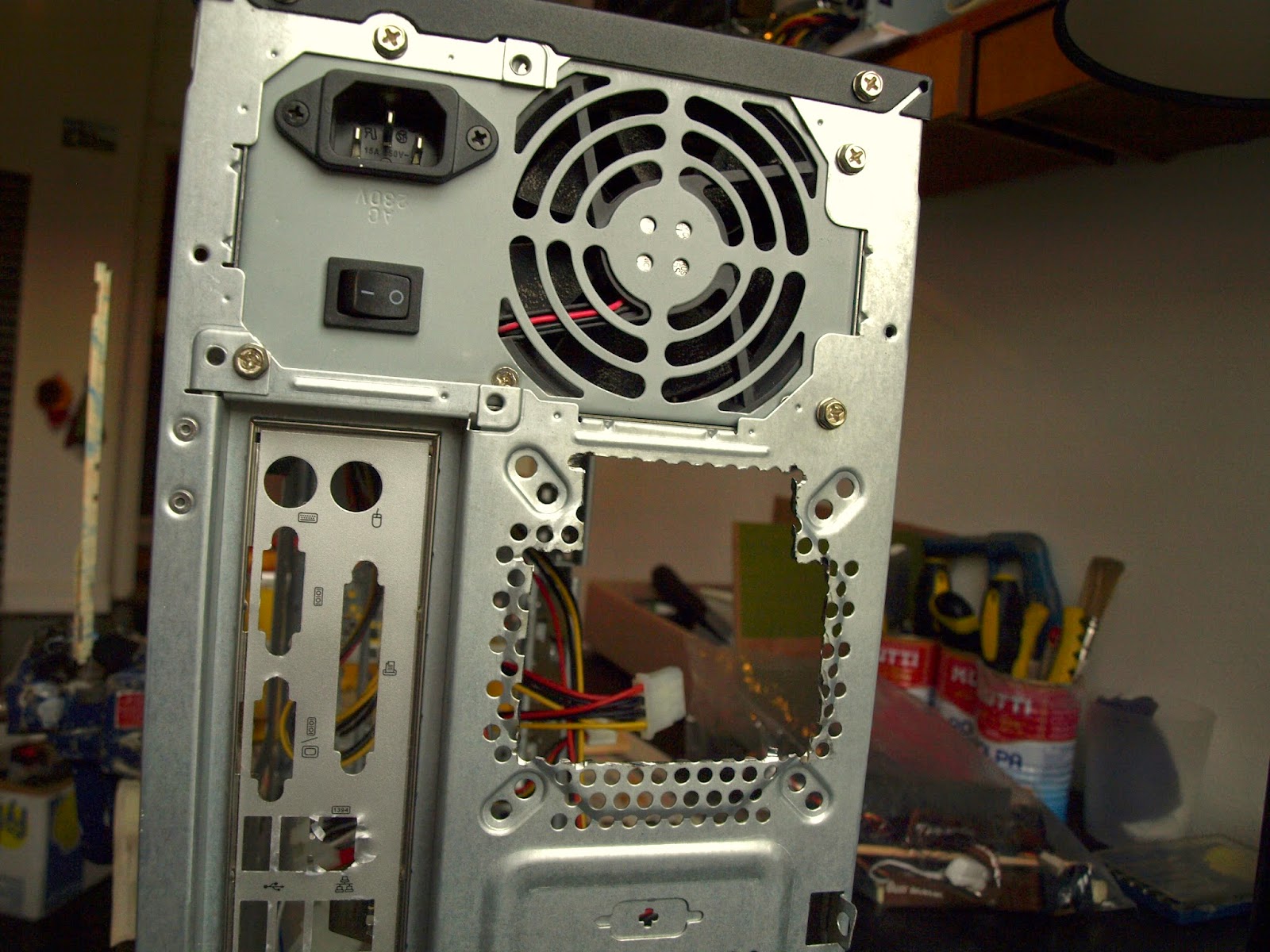
To get grills for the necessary air holes in the Detectron computer, the angle grinder was once again brought to play. The largest grills were cut off from the spare parts computer case that is lying around for Detectron transplantation. Further, the last potentiometer and speaker were removed from the Detectron lid.
Friday, October 31, 2014
Monday, October 20, 2014
It's alive!
Way too much time has passed since Detectron component arrival without testing that the ordered components actually work and add up to a computer. In this post, everything is hooked up for a quick test-boot or two. In this Frankensteinian construction, a rubber band was used to attach the chassifan to a piece of wood, that also got the honor of balancing the harddrive.
Since the case is yet to be done, one very important thing is missing: the power button. A power button for a modern computer is however nothing more than a fancy way of closing a circuit for half a second, or however long you take to push it. Thus, a power button can easily be faked by for example a screwdriver briefly touching the correct two pins on the motherboard. Yeah!
Beeeep.
Happy Detectron owner! While showing the boot setup, the Detectron fans did not make a sound, and CPU temperature was at a steady 33
°C.
power supply unit mounting
The following post contains one of the weirder solutions so far in the Detectron computer case construction. Even though the power supply unit (PSU) is one of the smallest on the market, fitting it into the Detectron case which is only 62 mm high has caused unhealthy amounts of pondering. A normal person would perhaps argue that fitting something which is 40 mm into a 62 mm slot should be within the range of the plausible, but the problem arrises when also considering the I/O button electronics that also need to sit in this space. On top of the PSU. Let's see how this has been solved.
Apart from requiring a slim mounting solution when mounted, there is also the issue of actually performing the mounting. In a regular computer case a PSU would be slided in into a perfectly sized compartment along the longest axis, and then screwed into place. However, with the PSU orientation needed in this case, the screw-holes of the PSU will be completely blocked - and it needs to go in from the top. To solve this, something very unorthodox has been done. First a holding point was created on the bottom of the case using two pieces of wood that were painstakingly carved to cradle the PSU. These were glued onto the case, but not until a strap was sewn (yes, sewn!) and attached to them, to a tightly as possible hold the PSU down and fast against the case floor.
This gave an extremely slimmed solution, which nevertheless fixates the PSU in all degress of freedom. Please inspect below! A scrap-salvaged old-school PSU power cable can also be seen.
Apart from requiring a slim mounting solution when mounted, there is also the issue of actually performing the mounting. In a regular computer case a PSU would be slided in into a perfectly sized compartment along the longest axis, and then screwed into place. However, with the PSU orientation needed in this case, the screw-holes of the PSU will be completely blocked - and it needs to go in from the top. To solve this, something very unorthodox has been done. First a holding point was created on the bottom of the case using two pieces of wood that were painstakingly carved to cradle the PSU. These were glued onto the case, but not until a strap was sewn (yes, sewn!) and attached to them, to a tightly as possible hold the PSU down and fast against the case floor.
This gave an extremely slimmed solution, which nevertheless fixates the PSU in all degress of freedom. Please inspect below! A scrap-salvaged old-school PSU power cable can also be seen.
Saturday, October 18, 2014
Airflow and inner layout
It has been somewhat hard to exactly imagine how everything would fit into place inside the small detectron case, but now with the components in hand and the first attachments made, things are starting to fall into place. One major issue has been how to allow airflow for cooling the CPU. Some inlets and outlets are needed, and they need to be placed to allow a reasonable path for the air to take, without any unnecessarily ugly holes in the case. See below the current sketch of how a detectron computer innards can be placed.

New in this design is putting the lid on hinges to allow easier opening of the case. This also has the dual benefit of allowing mounting of the CPU air vent and SSD on the lid, which reduces the need for other supporting constructs. Assembly of the hinges, lid and case will likely prove tricky, but it should work. Last, this sketch also shows how the inner power cord will be attached to the power supply unit, and then led to a secondary power connector beside the rest of the case inputs.
Tuesday, October 14, 2014
Sidesteps
The making of the Detectron computer is now well under way. In todays installment, a happy failure is described at producing mounting support for the motherboard. Using only four different power tools to manufacture the minute parts, success is finally achieved through an old wooden cork board frame.

The mounting of the motherboard is critical due to the very limited space in the case. It needs to sit 5 mm up so it's completely free from the case, but can't be much higher because space is still needed between the CPU-fan and case lid. Lastly, the motherboard should be attached by standard screws, so it's removable in case of failure.
Sometimes a desire arrises to take revenge on the family of desktop computers for all the pains caused through years of software development. In everyday life this urge is hard to let loose without colleagues having funny looks at you, but consider the following. Motherboard spacers are good for attaching motherboard at a perfect distance from whatever. The spacers are however not possible to glue directly onto the inside of a Detectron case, because of the small surface. It is therefore a completely legible option to scavenge some spacer mount points from an old desktop using a angle grinder - all in the name of reuse...
At a first glance, this vulgar approach could have worked, but it turns out that the quality of the handywork was subpar. Somehow one of the spacers was crushed in the grinding process, and the metal surface for gluing was not very even either.
Second plan consisted of a wooden supports, with drilled 5 mm holes into which spacers were carefully hammered. This had more success, and after angle grinding away the screw end of the spacers and sanding the wood, the four mount points were glued in place after many interations of attaching and detaching the motherboard and checking the position versus the I/O metal plate. Some might also note that the inside of the case has been cleaned using sander and knife to get a sufficiently low profile on the previous walls.
Monday, October 06, 2014
Making the cut
After a long wait, computer components have finally arrived. In this post, the poor detectron is relieved of all old purpose by merciless gutting by screwdriver and the marvelous oscillatory saw. The first mounting of the i5 CPU, RAM and fan in performed, and a small glimpse is given of the future.
First and easiest was the removal of all old junk from the inside of the lid. The front of the lid is naturally pretty much the same, but the backside now sports a cleaner yellow, for later attachment of the phidgets. There's still some stuff left. The speaker was bolted, and even after some furious sawing byMr. Dr. S it didn't give way. It will be removed later, by clever use of a metal drill. Then comes the ampere-gauge, which will be used to show CPU-load and other things. It was also confirmed to work in a very scientific validation of Ohm's law (does it really need a reference?). Finally there is the spirit level, which will stay, and something else (far left) that is bolted.
The oscillatory saw is a pretty crazy tool for sawing holes. Now the blade used was supposed to work for wood, but the detectron plastic didn't have any resistance to offer either. Cutting out the inner walls of the case was pretty straightforward, even though it would have been quite cramped with alternative tools.
After the simple work on the innards came the very scary part of making the I/O hole. As the saw was extremely keen on cutting stuff, a large margin was used to ensure that no extra plastic was removed. For the last millimeters a regular file was used. The last photo shows the motherboard backplate squezed in place.
For anyone ordering a computer in components, there is something almost ritual in the mounting of the processor and memory onto the motherboard. This was done under astrologically favorable conditions, and following vendor instructions with thermal paste and everything, after which the board was suggestively tried for fit inside the case.
So far so good. In the next installment, the hardship of cramming a too small detectron box full of electronics will be mused, while airflow and construction work in considered.
First and easiest was the removal of all old junk from the inside of the lid. The front of the lid is naturally pretty much the same, but the backside now sports a cleaner yellow, for later attachment of the phidgets. There's still some stuff left. The speaker was bolted, and even after some furious sawing by
The oscillatory saw is a pretty crazy tool for sawing holes. Now the blade used was supposed to work for wood, but the detectron plastic didn't have any resistance to offer either. Cutting out the inner walls of the case was pretty straightforward, even though it would have been quite cramped with alternative tools.
After the simple work on the innards came the very scary part of making the I/O hole. As the saw was extremely keen on cutting stuff, a large margin was used to ensure that no extra plastic was removed. For the last millimeters a regular file was used. The last photo shows the motherboard backplate squezed in place.
For anyone ordering a computer in components, there is something almost ritual in the mounting of the processor and memory onto the motherboard. This was done under astrologically favorable conditions, and following vendor instructions with thermal paste and everything, after which the board was suggestively tried for fit inside the case.
So far so good. In the next installment, the hardship of cramming a too small detectron box full of electronics will be mused, while airflow and construction work in considered.
Friday, September 19, 2014
Intermission
The recent lack of progress has been fuelled by two parallel causes. Mr S, collegue and partner in crime, had to make a trip to Europe's mountains over a week. Also, central components for the Detectron computer, like the motherboard, are still being shipped (although probably by truck). While waiting, the current workspace was put to the test in restoring an old Sansui Stereo (1974), which is described in this post.
Although much of the hardware is still in transit, the tools, multimeters, and the phidget USB I/O cards have arrived. To complement the sterile, efficiency seeking table, a 60s string shelf has been filled with orchids, porcelain och cooking books.
The Sansui Stereo receiver 771 was bought from ReHIFI a few years ago. It has a really warm and cozy sound that shines especially when playing classic and jazz. However, it did have problems with dropping one of the speakers every now and then, and making weird noises when turning the volume or equalizer knobs. The amateur diagnosis is that the potentiometers and inputs/outputs probably have become dirty during the last 40 years, and maybe a simple cleaning could fix things.
It turned out that one of the hardest parts in the restoration was to actually break into the stereo. After removing the wooden case with four simple screws, it took several hours to figure out that the front panel was actually attached behind the knobs, apart from the two screws on the top. Apparently the principle of single purpose does not apply to vintage stereos, and combining key structural support with sensitive input is not a problem. Behind the front panel could be seen the I/O circuit card that handled the knobs and buttons, along with the sought potentiometers. Unfortunately there was a lack of pictures taken of the inner workings, likely due to the excitement involved at this point combined with diverse family members requiring attention.
The insides of the stereo was first dusted using a vacuum cleaner and a paint brush (method taken from this post). There was surprisingly a lot of dust, although the domestic surroundings that are the stereos natural habitat are stringently clean... ahum. After this the potentiometers were cleaned with pressurized air, followed by a round of potentiometer cleaning spray. All inputs and outputs were similarly treated but using the regular contact cleaning spray.
Typically old stereos need a replacement of all old paper capacitors, since these loose their function with age. However, since the stereo has a very nice sound as it, it seems very likely that this was done at ReHIFI before the purchase. The capacitors also look newer that the rest of the electronics. Also take note of the highly analog (string-driven) radio tuner dial.
Before reassembly, a sort of successful attempt was made at replacing the old power cord with a new, grounded one. This did work out, but involved some very poor soldering, which is shown in a figure below to encourage any other enthusiasts. There was also an effort to replace the backlights for the tuner display into LEDs, but it turned out that they were operating on AC (multimeters are great!), which made the needed circuit construction and soldering a bit too scary compared to the small gains.
Although much of the hardware is still in transit, the tools, multimeters, and the phidget USB I/O cards have arrived. To complement the sterile, efficiency seeking table, a 60s string shelf has been filled with orchids, porcelain och cooking books.
The Sansui Stereo receiver 771 was bought from ReHIFI a few years ago. It has a really warm and cozy sound that shines especially when playing classic and jazz. However, it did have problems with dropping one of the speakers every now and then, and making weird noises when turning the volume or equalizer knobs. The amateur diagnosis is that the potentiometers and inputs/outputs probably have become dirty during the last 40 years, and maybe a simple cleaning could fix things.
It turned out that one of the hardest parts in the restoration was to actually break into the stereo. After removing the wooden case with four simple screws, it took several hours to figure out that the front panel was actually attached behind the knobs, apart from the two screws on the top. Apparently the principle of single purpose does not apply to vintage stereos, and combining key structural support with sensitive input is not a problem. Behind the front panel could be seen the I/O circuit card that handled the knobs and buttons, along with the sought potentiometers. Unfortunately there was a lack of pictures taken of the inner workings, likely due to the excitement involved at this point combined with diverse family members requiring attention.
The insides of the stereo was first dusted using a vacuum cleaner and a paint brush (method taken from this post). There was surprisingly a lot of dust, although the domestic surroundings that are the stereos natural habitat are stringently clean... ahum. After this the potentiometers were cleaned with pressurized air, followed by a round of potentiometer cleaning spray. All inputs and outputs were similarly treated but using the regular contact cleaning spray.
Typically old stereos need a replacement of all old paper capacitors, since these loose their function with age. However, since the stereo has a very nice sound as it, it seems very likely that this was done at ReHIFI before the purchase. The capacitors also look newer that the rest of the electronics. Also take note of the highly analog (string-driven) radio tuner dial.
Before reassembly, a sort of successful attempt was made at replacing the old power cord with a new, grounded one. This did work out, but involved some very poor soldering, which is shown in a figure below to encourage any other enthusiasts. There was also an effort to replace the backlights for the tuner display into LEDs, but it turned out that they were operating on AC (multimeters are great!), which made the needed circuit construction and soldering a bit too scary compared to the small gains.
In conclusion, the issues experienced before restoration seem to have pretty much vanished. The stereo, now coupled to a Bluetooth receiver, played very diverse music flawlessly for four hours yesterday. The only thing that's still a nuisance is that one of the three pairs of speaker outputs still drops a speaker occasionally, but every old device needs it's own personality.
Subscribe to:
Posts (Atom)